When most people think of waves, they imagine something like an ocean wave… it moves through the water and isn’t confined to one area. Some waves don’t travel at all – they are called standing waves.


Please login or register to read the rest of this content.

One common misconception is the idea that noes and antinodes are the same as the crest and trough of a wave. They’re not. A node is a place on the wave that is permanently at rest. An antinode is where the wave is at its maximum (it will travel through a large up and a large down displacement).
Please login or register to read the rest of this content.


Standing waves are basically two waves traveling in opposite directions that constructively interfere with each other so it looks like the whole system is moving in simple harmonic motion.
Please login or register to read the rest of this content.


Standing wave machines are fun to make because they are easy to build and amazing to watch! Here’s a simple one you can make on your own using the materials from the previous lessons in electricity.


Please login or register to read the rest of this content.

It’s easy to calculate the frequency, period, wavelength and speed of waves at different harmonics.
Please login or register to read the rest of this content.


When a wave travels from one medium to another, like sound waves traveling in the air and then through a glass window pane, it crosses a boundary. Whether the wave continues to the new medium (and even how it goes through), or whether it bounces and reflects back, or a bit of both depends on the boundary.
Please login or register to read the rest of this content.


Straight waves are what happens when something  moves back and forth in a medium like water. These are interesting when they hit a diagonal plane barrier, because when the incident wave reaches the barrier, the waves always reflect at the same angle that they approached the barrier with (called the Law of Reflection).
Please login or register to read the rest of this content.


Waves bend when they go from one medium to another when the speed changes. It’s a really important topic in light (not so much with sound), because it’s how lenses, eyes, cameras, and telescopes work. The bending of sound waves happens naturally in the air above the earth when it’s warmer than the surface of the earth. The sound waves that travel through the warmer air are faster and the ones that travel through cooler air are slower. When the sound waves go from warmer to cooler air (less dense to more dense air), they become bent back down toward the surface.
Please login or register to read the rest of this content.


When waves pass around small (we’re talking small compared to the wavelength of the wave) objects, they diffract. People in the audience of a concert can hear really well if they are sitting right behind a pillar because the sound waves are large enough to bend around it (which is actually because of both diffraction and reflection effects). Diffraction helps sound bend around obstacles. You can sometimes hear conversations around corners because of diffraction.
Please login or register to read the rest of this content.


Often two (or more) waves travel through the same spot. If you’ve ever listened to an orchestra, you’re hearing the sounds from many different instruments all playing at the same time. If more than two boats are on the lake, their wakes churn up the water together. Here’s how we handle this in physics…
Please login or register to read the rest of this content.


What if two waves of the same wavelength and amplitude travel in the same direction along a stretched string? What will the string look like? We know about the idea of superposition adding the waves together, but what does the string actually look like?
Please login or register to read the rest of this content.


When two waves have an increase in displacement when they  interact, it’s constructive interference.
Please login or register to read the rest of this content.


Destructive interference happens when two waves have opposite displacements. The pulses don’t destroy each other (as the name implies), but rather they cancel out the effect of each other when they interact with each other.
Please login or register to read the rest of this content.


In previous lessons we’ve learned that energy is the ability to do work, and that work is moving something a distance against a force. The concept of energy is fairly easy to see as far as lifting things or pushing things go. We are exerting energy to lift a box against the force of gravity. We are exerting energy to pedal our bike up a hill. But how does this energy stuff relate to light, electricity, or sound? What’s moving against a force there?


Please login or register to read the rest of this content.

Damping is when a spring, swing, or other vibrating object loses its energy over time. It means that without adding energy into the system, like pumping on a swing or hitting a drum head, the object will eventually come to its non-vibrating (equilibrium) position.


Imagine the kid on the swing again. Why does the kid move past the equilibrium point without stopping?
Please login or register to read the rest of this content.


The concept of frequency is very important to understanding energy. When it comes to electromagnetic waves it is frequency that determines whether the wave is radio, light, heat, microwave or more. It’s all the same type of energy, it’s the frequency that determines what that energy actually does. With sound energy the frequency determines the pitch of the sound.


Please login or register to read the rest of this content.

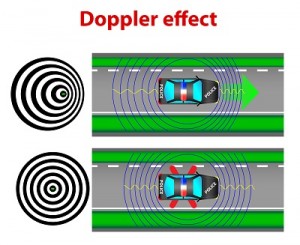
Imagine a police car on the side of the road with lights and sirens on full blast. You’re also parked and you hear the same frequency (say 1,000 Hertz) of the siren. However, if you’re driving at 75 mph toward the police car. you’re going to hear a higher frequency (1096 Hz), and if you’re driving away at 75 mph, you’re going to hear a lower frequency of 904 Hz. Why is that?
Please login or register to read the rest of this content.


The period is the time it takes for one full cycle to complete itself and is measured in seconds per cycle. The frequency is the number of cycles that are make in a period of time, and is measured in cycles per second.


Please login or register to read the rest of this content.

The frequency is the number of cycles that are made in a given period of time, like 10 swings in 5 seconds, and is measured in cycles per second. The period is the inverse of the frequency, given by this equation: T = 1/ν.


Please login or register to read the rest of this content.

Amplitude is how high or low the wave is from its original equilibrium position. (not vibrating). How high can you get the swing to go? How far does the car system spring travel over that bump? All these are the amplitude of the vibration.


Please login or register to read the rest of this content.

The restoring force slows down the object as it moves from its resting but speeds it up when it heads back to the resting position, and that’s what creates the vibration. We’re going to take a look at the forces in a pendulum from the point of view of Newton’s Laws.
Please login or register to read the rest of this content.


There’s more than one way to solve physics problems… and by looking at the total mechanical energy of the system, you’ll be able to solve much more complicated pendulum problems with ease.


Please login or register to read the rest of this content.

You’ll need a pendulum for this experiment. A pendulum is really nothing more than a weight at the end of something that can swing back and forth. The easiest way to make one is to get a string and tape it to the edge of a table. (The string should be long enough so that it swings fairly close to the ground.) Tie a weight to the bottom of your string and you’ve got a pendulum.
Please login or register to read the rest of this content.


How are pendulums like springs? They both vibrate, but how you model them on paper is a little different. Let’s take a look at how you handle springs and what their periodic nature looks like:
Please login or register to read the rest of this content.


Since we can’t see soundwaves as they move through the air, we’re going to simulate one with rope and a friend. This will let you see how a vibration can create a wave. You’ll need at least 10 feet of rope (if you have 25 or 50 feet it’s more fun), a piece of tape (colored if you have it), a slinky, and a partner. Are you ready?


Please login or register to read the rest of this content.

Click here to go to next lesson on Motion of Waves.

This is a recording of a recent live teleclass I did with thousands of kids from all over the world. I’ve included it here so you can participate and learn, too!


Sound is a form of energy, and is caused by something vibrating. So what is moving to make sound energy?


Molecules. Molecules are vibrating back and forth at fairly high rates of speed, creating waves. Energy moves from place to place by waves. Sound energy moves by longitudinal waves (the waves that are like a slinky). The molecules vibrate back and forth, crashing into the molecules next to them, causing them to vibrate, and so on and so forth. All sounds come from vibrations.


Materials:


  • 1 tongue-depressor size popsicle stick
  • Three 3″ x 1/4″ rubber bands
  • 2 index cards
  • 3 feet of string (or yarn)
  • scissors
  • tape or hot glue
Please login or register to read the rest of this content.

Click here to go to next lesson on Energy of a Wave.

Since  the particles don’t travel with the wave, what does a wave carry? Waves transport energy, not particles (or matter).
Please login or register to read the rest of this content.


Some waves need a medium to travel through while others do not. Mechanical waves need a medium for the wave to travel through to transport energy. Ocean waves, jump ropes, pendulums, sound, and waves in a stadium are all examples of mechanical waves.
Please login or register to read the rest of this content.


The words particle and wave are two words you’ll see in nearly every area of physics, but they are actually very different from each other. A particle is a tiny concentration of something that can transmit energy, and a wave is a broad distribution of energy that fills the space it passes through. We’re going to look at particles in more depth later, and instead focus on understanding waves.
Please login or register to read the rest of this content.


Humming birds are really fascinating, because they can beat their wings so fast! Here’s a quick way to calculate the frequency and period of a humming bird’s wings.
Please login or register to read the rest of this content.


Kids love swings, and it’s amazingly simple to find the frequency and period of the swing. Here’s how…
Please login or register to read the rest of this content.


Sound is a type of energy, and energy moves by waves. So sound moves from one place to another by waves; longitudinal waves to be more specific. So, how fast do sound waves travel? Well, that’s a bit of a tricky question. The speed of the wave depends on what kind of stuff the wave is moving through. The more dense (thicker) the material, the faster sound can travel through it.
Please login or register to read the rest of this content.


Sound moves faster in solid objects than it does in air because the molecules are very close together in a solid and very far apart in a gas. For example, sound travels at about 760 mph in air, 3300 mph in water, 11,400 mph in aluminum, and 27,000 mph in diamond!
Please login or register to read the rest of this content.


An echo is when a wave travels through one medium (like air) and then meets a different medium (like a cave wall). The sound wave bounces and reflects back to you.
Please login or register to read the rest of this content.


Let’s do a couple of simpler sample problems, and then I’ll show you how to do problems that are more complex and involve higher level math. First, let’s take a look at the wings of a bird in flight…
Please login or register to read the rest of this content.


Ocean waves travel on the surface of the water can be observed and measured. Let’s try one just before a storm…
Please login or register to read the rest of this content.


Ever gotten sea sick? It’s usually because the motion of what your body detects is different from what your eyes see. Let’s take a look at how you can calculate the wave speed by watching two boats bobbing up and down (without getting sick).
Please login or register to read the rest of this content.


Waves traveling on a tight string, like a climbing rope, are dependent on only two things: the tension of the rope and a physical property of the rope (like what it’s made out of, the diameter, etc.).
Please login or register to read the rest of this content.


Now it’s time for a little more math because the physics problems are going to get a little harder.
Please login or register to read the rest of this content.


If a wave can travel through mediums like air, water, strings, rocks, etc., then it makes sense that as the wave moves through these mediums, the tiny particles that make up the medium will also vibrate. In order for this to happen, the medium has to have a way for energy (both potential and kinetic) to be stored, so the medium has both inertia and elasticity.
Please login or register to read the rest of this content.


It’s easy to see how the current flows through a circuit that has only one component, like one LED connected to the battery. If it’s a 3 Volt battery, then there’s 3 Volts across the LED also.


But what if there are two or three LEDs? How does the voltage look across each one? What if the LEDs are different sizes? Does it matter how you hook them up, meaning does one way make the LED last monger or glow brighter? Let’s take a look at the difference between series and parallel connections.


Please login or register to read the rest of this content.

Each electrical component is connected so that there’s only one option for the current to flow. There’s no branches or alternate routes for the electricity… it’s only got one way to move through the circuit. When you add more electrical components, like motors or LEDs to this circuit, the overall resistance in the circuit decreases since there’s only one path for the current.


Please login or register to read the rest of this content.

Each device, like a motor or LED, has its own branch lines in a parallel circuit, which means that the electricity has many different ways that it can travel along the circuit lines. When scientists and engineers draw electrical diagrams, they put one electric component on each branch, even if in reality there’s more than one when you actually build the thing.


Please login or register to read the rest of this content.

Current and charge aren’t quite the same thing. Current is rate that charge goes through a circuit (just like acceleration is the rate of change in velocity… acceleration and velocity aren’t the same thing either, but they are related). Remember, charge doesn’t get used up by electrical components like LEDs or resistors.


Please login or register to read the rest of this content.

One more thing to note about the difference between series and parallel circuits is that in a parallel circuit, the current in each branch can be different, but they all add up to be the same everywhere once you reduce the branches into a single branch. Just like the water analogy, when you connect the main hose into five different smaller hoses, the sum of all five is going to equal flow through the main hose.


Please login or register to read the rest of this content.

Now let’s take a look at how Ohm’s Law and Power work together:


Please login or register to read the rest of this content.

Physics equations are pretty useless unless you really understand how to apply them… that’s when the real magic happens. Here’s an example of how to apply Ohm’s law intelligently and easily.


Please login or register to read the rest of this content.

We’re about to jump into making a lot of really cool experiments with different electrical components, but before we do, let’s recap what we’ve covered so you’re sure not to miss any important concepts.


Please login or register to read the rest of this content.

It’s easy to get sucked into doing math and equations all day without understanding how it applies to the real world. Let’s take a look at how to actually hook up series and parallel circuits in everyday life, and how they are different, and when to use each one…


Please login or register to read the rest of this content.

Although you can’t see electricity, you can certainly detect its effects – a buzzer sounding, a light flashing, a motor turning… all of these happen because of electricity. Which is why electricity experiments are among the most frustrating. You can’t always tell where the problem is in a circuit that refuses to work right.


We’re going to outline the different electronic components (resistors, capacitors, diodes, transistors, etc) so you get a better feel for how to use them in a circuit. While we’re not going to spend time on why each of these parts work (which is a topic best reserved for college courses), we are going to tackle how to use them to get your circuit to do what you want. The steps to building several different electronics projects are outlined very carefully so you can really understand this incredible micro-world.


In this video, you’ll learn how to identify each electronic component.  You’ll also learn how to use a breadboard to quickly build circuits that can be easily changed.  Plus, you’ll learn how to make sure you don’t damage your components.


Before you use a breadboard, you need to know how the “holes” in it connect to each other.  Once you get this, they’re easy to use, but until you understand their secret, they can be totally confusing.  Be sure to pay attention to this part, and it will make things a lot easier.  Once you have this down, you’ll wire up a few simple circuits on the breadboard just to try out your new knowledge.


Which part is which? Click here to access a reference sheet so you can tell which resistor is which.


Please login or register to read the rest of this content.

Click here to go to your next lesson on Series Switches.

Switches are a lot of fun, they allow us to control when a circuit is on and when it’s off. In this experiment we’ll see how two switches can be connected in series to control when a single device is on or off.


Please login or register to read the rest of this content.


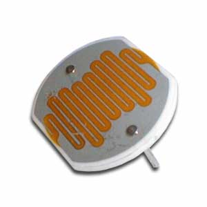
In this circuit, we’re going to use a special kind of resistor, called a CdS photocell to detect light and dark.  When light is shined on the photocell, the LED will light up.  When it is dark, the LED goes out.  And with just a little light, the LED is dim.  Remember the explanation of how a transistor works?  We talked about having a small voltage (or current) control a larger one, kind of like turning the knob on a light switch dimmer in your house?  That’s what this circuit is doing.


The photocell is a kind of resistor that changes it’s resistance depending on how light or dark it is.  In this circuit, when it is light, the photocell delivers more current to the base lead of the transistor.   When this happens, the transistor allows more voltage to flow from the emitter lead to the collector lead, which in turn lights up the LED.  One resistor are simply used to reduce the amount of current that goes into the transistor (so it doesn’t get too much current)  if the photocell has a really low resistance because of how much light is on it.  The other one is called a pull-down resistor.  Think of it like a door closer spring for electricity.  A door closer closes the door when you let go of it (instead of leaving the door to sway in the wind).  A pull-down resistor makes sure that when the transistor is “off”, it will “spring” toward a connection to the negative side of the battery (a pull-up makes it spring toward the positive).


Please login or register to read the rest of this content.

Click here to go to your next lesson on Light De-actuated Circuit.

Make sure you’ve already made the Light Actuated Circuit before starting this project!


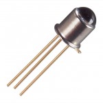
Photoresistors (also called CdS photocells) are made of a material that reacts with light, very similar to solar cells.  When light hits the material, it knocks a few electrons loose. When you hook up the cell to a circuit, the electrons now have a place to go, and electricity flows through your wires. You’ll notice your CdS cell works when you shine a light on it from either the front side or the back side. If you want to use a phototransistor, make a note as to the frequency of light it’s been tuned to – some will only work with IR light (like your remote control or sunlight).


In this circuit, the LED is actuated only when the photoresistor is dark. If you want a faster response to your light, you can substitute a phototransistor for the photoresistor (CdS cell) and adjust the value of the 1-kOhm resistor (change it lower or higher, or use a potentiometer) to control the sensitivity.


This is basically the same as the light-actuated circuit.  The difference is that the transistor is connected to control power to the LED in the opposite way as the light-actuated circuit.  So, as there is more light on the photocell (and the base lead gets more current), the voltage to the transistor is reduced.


Click here for Unit 14 (Lesson 1) schematics.


Notice what is the same in the circuit, and what is different.


Please login or register to read the rest of this content.

Click here to go to your next lesson on How to Read Schematics.

Do you remember the first time you tried to read a map? There were all those weird symbols and curving lines that you had to figure out before you could get anywhere. Electric circuits are kind of the same way… people use schematic diagrams to write down how their circuit is wired so others can build it, too.


Please login or register to read the rest of this content.


This Flashing Circuit used to be a real ‘wowser!’ with students before LEDs become commonplace (around 1995). You’re going to build a circuit that has a control knob that will allow you to set the flash speed of the LED. You can try different LEDs or mini-lamps to see what kind of an effect you get. Are you ready?


NPN and PNP transistors are similar in that when current is applied to the base, electricity flows through them.  But, they way they are used is different.  NPN transistors are often used to control whether a circuit is completed by connecting it to ground or not, where PNP control the positive current going into a device (or portion of a circuit).  NPN transistors are often used where larger currents need to be controlled, because it’s easier for a transistor to control the ground side of a circuit than the plus power side of it.


So, why does the LED flash?  Remember, a capacitor is like a storage tank for electricity.  You fill it up, then empty it out.  But, it takes time to fill up and empty.  This circuit uses the time it takes to fill and empty as a delay for turning the LED on and off.  How fast it fills up depends on the value of the resistor that is connected to it.  We’re using a variable resistor, so we can adjust how fast it fills up, and thus adjust the flash rate.


Click here for Unit 14 (Lesson 1) schematics.


Please login or register to read the rest of this content.

Click here to go to your next lesson on Audible Probes.

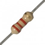
Resistors look like candy-striped hot dogs. Their job is to limit current to keep sensitive electronics from being overloaded. If you break open a resistor, you’ll find a pile of graphite. If you have a digital multimeter, draw a line on a sheet of paper with a graphite pencil, and place one probe near the end of the line. You can measure the change in resistance along the line with your other multimeter probe!


Make sure you’ve made the Light Flasher before starting this circuit. This circuit, the Audible Light Probe, is actually a very sensitive circuit that will emit all sorts of sounds reminiscent of junior high school boys locker rooms. The frequency from the speaker will change as the light intensity changes. One of the neat features about this circuit is that it will allow you to test different transistors (both PNP and NPN) to see (hear) the changes. You can also play with the capacitor and resistor values to change the range.


Click here for Unit 14 (Lesson 1) schematics.


TIP: If your tones won’t stop, or are too high to hear, try operating your circuit in a very dark room before adding the light. Can you get your speaker to *click*?


Please login or register to read the rest of this content.

Click here to go to your next lesson on Lie Detectors.

Lie Detectors are electronic circuits that are able to measure your skin’s resistance. When you sweat (or if your skin is wet), the resistance is different than if it’s dry.


However since most people don’t sweat when they lie, this type of detector isn’t the most reliable type of detector around, but it’s one of the simplest to create. We’re going to build one from simple electronic components like resistors, capacitors, and transistors.


Our lie detector uses a speaker that changes pitch depending on the resistance of your skin – it’s much more entertaining than blinking an LED on or off. You can think of this circuit as more of a skin humidity indicator. Are you ready?


Please login or register to read the rest of this content.

This is a recording of a recent live teleclass I did with thousands of kids from all over the world. I’ve included it here so you can participate and learn, too! (Click here if you’re looking for the more recent version that also includes Chemical Engineering.)


When you think of slime, do you imagine slugs, snails, and puppy kisses? Or does the science fiction film The Blob come to mind? Any way you picture it, slime is definitely slippery, slithery, and just plain icky — and a perfect forum for learning real science. But which ingredients work in making a truly slimy concoction, and why do they work? Let’s take a closer look…


Materials:


  • Sodium tetraborate (also called “Borax” – it’s a laundry whitener) – about 2 tablespoons
  • Clear glue or white glue (clear works better if you can find it) – about 1/2 cup
  • Yellow highlighter
  • Pliers or sharp razor (with adult help). (PREPARE: Use this to get the end off your highlighter before class starts so you can extract the ink-soaked felt inside. Leave the felt inside highlighter with the end loosely on (so it doesn’t dry out))
  • Resuable Instant Hand Warmer that contains sodium acetate (Brand Name: EZ Hand Warmer) – you’ll need two of these
  • Scissors
  • Glass half full of COLD water (PREPARE: put this in the fridge overnight)
  • Mixing bowl full of ice (PREPARE: leave in freezer)
  • Salt
  • Disposable aluminum pie place or foil-wrapped paper plate
  • Disposable cups for solutions (4-6)
  • Popsicle sticks for mixing (4-6)
  • Rubber gloves for your hands
  • Optional: If you want to see your experiments glow in the dark, you’ll need a fluorescent UV black light (about $10 from the pet store – look in cleaning supplies under “Urine-Off” for a fluorescent UV light). UV flashlights and UV LEDs will not work.
Please login or register to read the rest of this content.

As electrons move through a load in an electric circuit (devices like a LED, buzzer, motor, etc.), they experience resistance (even through the wire itself), which corresponds to a drop in energy . This drop in energy is referred to as a voltage drop.  Resistance hinders the flow of electrons, even in the water itself.  You can think of resistance as the friction between the water and the pipe along the inside of the pipe.


The pipe, just like the wire, has a certain diameter and length. The longer the wire, the more resistance the electron will encounter, just as with a long pipe of water. If you increase the pipe diameter, more water will flow through it. The thicker the wire, the more current flows through it. The amount of resistance the charge encounters also depends on what the wire is made out of. Certain materials are more electrically conductive than others, with silver, copper and gold being at the very low end of electrical resistance (which is why most wires are made from copper, which is the least expensive of the three).


Please login or register to read the rest of this content.

Let’s see how a length of wire changes its resistance depending on how long it is:


Please login or register to read the rest of this content.

Resistors are a very important part of electronics, in fact without them we wouldn’t even have electronics. Resistors help us control the flow of current through a circuit and protect components from being damaged. This video talks about what resistors are, how to read them, and how to use them.


Please login or register to read the rest of this content.

Click here to go to your next lesson on Potentiometers.

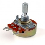
potSo now you know how to hook up a motor, and even wire it up to a switch so that it goes in forward and reverse. But what if you want to change speeds? This nifty electrical component will help you do just that.


Once you understand how to use this potentiometer in a circuit, you’ll be able to control the speed of your laser light show motors as well as the motors and lights on your robots. Ready?


Please login or register to read the rest of this content.

meterOne of the most useful tools a scientist can have! A digital multimeter can quickly help you discover where the trouble is in your electrical circuits and eliminate the hassle of guesswork. When you have the right tool for the job, it makes your work a lot easier (think of trying to hammer nails with your shoe).

We'll show you how to get the most out of this versatile tool that we're sure you're going to use all the way through college. This project is for advanced students.

Please login or register to read the rest of this content.

Click here to go to your next lesson on Ohm's Law.


One of the most important equations in current electricity is: V = IR. With one glance, you can see how current, voltage, and resistance are related to each other. If the current decreases, so does the voltage. Charge  mores when the resistance decreases.


Please login or register to read the rest of this content.

Now let’s take a look at a couple of sample calculations so you really understand how to do this…


Please login or register to read the rest of this content.

There are two main equations for power in the field of current electricity:


P = I2 R


P = V2/R


where P = power (watts), V = voltage (volts), R = resistance (ohms), I = current (amps)


Please login or register to read the rest of this content.

I do have a LOT of hair on my head. Here’s a neat way to figure out how much current I use every morning I fire up the hair dryer:


Please login or register to read the rest of this content.

Do you like toast? Here’s how much current it takes to transform ordinary bread into crunchy toast:


Please login or register to read the rest of this content.

What’s the difference between a 60W at a 120W bulb? Let’s take a look…


Please login or register to read the rest of this content.

This is a recording of a recent live teleclass I did with thousands of kids from all over the world. I’ve included it here so you can participate and learn, too!


You’ll discover how to boil water at room temperature, heat up ice to freeze it, make a fire water balloon, and build a real working steam boat as you learn about heat energy. You’ll also learn about thermal energy, heat capacity, and the laws of thermodynamics.


Materials:


  • cup of ice water
  • cup of room temperature water
  • cup of hot water (not scalding or boiling!)
  • tea light candle and lighter (with adult help)
  • balloon (not inflated)
  • syringe (without the needle)
  • block of foam
  • copper tubing (¼” diameter and 12” long)
  • bathtub or sink
  • scissors or razor
  • fat marker (to be used to wrap things around, not for writing)
Please login or register to read the rest of this content.

Imagine you have two metal plates that are parallel to each other, and one is positively charged ad the other is negatively charged. The direction of the electric field created by these two charged places is from the positive toward the negative plate. (Imagine placing a positive test charge int he field… which way would it go? Away from the positive plate and toward the negative plate… so that’s the direction of the electric field.) Now imagine connecting the two plates with a metal wire. What do you think would happen?


Please login or register to read the rest of this content.

An electrical circuit is like a NASCAR raceway.  The electrons (racecars) zip around the race loop (wire circuit) superfast to make stuff happen. Although you can’t see the electrons zipping around the circuit, you can see the effects: lighting up LEDs, sounding buzzers, clicking relays, etc.


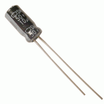
There are many different electrical components that make the electrons react in different ways, such as resistors (limit current), capacitors (collect a charge), transistors (gate for electrons), relays (electricity itself activates a switch), diodes (one-way street for electrons), solenoids (electrical magnet), switches (stoplight for electrons), and more.  We’re going to use a combination diode-light-bulb (LED), buzzers, and motors in our circuits right now.


A CIRCUIT looks like a CIRCLE.  When you connect the batteries to the LED with wire and make a circle, the LED lights up.  If you break open the circle, electricity (current) doesn’t flow and the LED turns dark.


LED stands for “Light Emitting Diode”.  Diodes are one-way streets for electricity – they allow electrons to flow one way but not the other.


Remember when you scuffed along the carpet?  You gathered up an electric charge in your body.  That charge was static until you zapped someone else.  The movement of electric charge is called electric current, and is measured in amperes (A). When electric current passes through a material, it does it by electrical conduction. There are different kinds of conduction, such as metallic conduction, where electrons flow through a conductor (like metal) and electrolysis, where charged atoms (called ions) flow through liquids.


Please login or register to read the rest of this content.

Click here to go to your next lesson on Detecting Current!

Galvanometers are coils of wire connected to a battery. When current flows through the wire, it creates a magnetic field. Since the wire is bundled up, it multiplies this electromagnetic effect to create a simple electromagnet that you can detect with your compass.
Please login or register to read the rest of this content.


switch-zoomMake yourself a grab bag of fun things to test: copper pieces (nails or pipe pieces), zinc washers, pipe cleaners, Mylar, aluminum foil, pennies, nickels, keys, film canisters, paper clips, load stones (magnetic rock), other rocks, and just about anything else in the back of your desk drawer.


Certain materials conduct electricity better than others. Silver, for example, is one of the best electrical conductors on the planet, followed closely by copper and gold. Most scientists use gold contacts because, unlike silver and copper, gold does not tarnish (oxidize) as easily. Gold is a soft metal and wears away much more easily than others, but since most circuits are built for the short term (less than 50 years of use), the loss of material is unnoticeable.
Please login or register to read the rest of this content.


Click here to go to your next lesson on requirements for a circuit!

You need two important things for an electric circuit: first you need a closed conductive path that goes from the positive to the negative terminal of the battery. When I teach this activity to kids, there’s always a couple that try to light up the LED just using the LED and wires (they forget about the battery completely!) You always need a power source in the circuit in order for charges to flow. The charges only flow through something that conducts electricity. Sometimes kids forget about the conductive part, and just try to touch the plastic coating on the wires to the LED and are frustrated when it doesn’t work right. It must be a closed conductive loop.


Please login or register to read the rest of this content.

This is a recording of a recent live robotics teleclass I did with thousands of kids from all over the world. I’ve included it here so you can participate and learn, too!


We’ll cover topics in electricity, magnetism, electrical charges, robot construction, sensors and more by building several projects together. For now, just watch the video and if you already have the materials to build the projects, feel free to do it along with me. If not, don’t worry… we’ll get to these projects soon in the course.


Please login or register to read the rest of this content.

If this next part is too confusing, just skip over it. I did want to let you know (for those of you who have spotted it already) that there’s a big problem with the positive test charge model we’ve been using. Well, it’s kind of a problem, but not really a big one once you get used to the idea.


Please login or register to read the rest of this content.

In electric circuits, the charge carriers are electrons, which are already inside the wire itself. The battery doesn’t add extra electrons to the circuit to make it go… the electrons inside the wires are already there. The battery provides an electric potential difference that signals the electrons to start moving, and this signal travels at the speed of light (or close to it), and then the electrons start moving (quite a bit slower than the speed of light). This means that electrons don’t have to start at the battery and them go all the way to the light before the light bulb lights up, because the electrons inside the filament itself are the ones that start glowing when they get the signal to start moving.


Please login or register to read the rest of this content.

knifeswitchWhen you turn on a switch, it’s difficult to really see what’s going on… which is why we make our own from paperclips, brass fasteners, and index cards.


Kids can see the circuit on both sides of the card, so it makes sense why it works (especially after doing ‘Conductivity Testers’).


SPST stands for Single Pole, Single Throw, which means that the switch turns on only one circuit at a time. This is a great switch for one of the robots we’ll be making soon, as it only needs one motor to turn on and off.
Please login or register to read the rest of this content.


 Click here to go to your next lesson on Electric Circuit Loads!

Imagine you have two magnets. Glue one magnet on an imaginary record player (or a ‘lazy susan’ turntable) and hold the other magnet in your hand. What happens when you bring your hand close to the turntable magnet and bring the north sides together?


The magnet should repel and move, and since it’s on a turntable, it will circle out of the way. Now flip your hand over so you have the south facing the turntable. Notice how the turntable magnet is attracted to yours and rotates toward your hand. Just as it reaches your hand, flip it again to reveal the north side. Now the glued turntable magnet pushes away into another circle as you flip your magnet over again to attract it back to you. Imagine if you could time this well enough to get the turntable magnet to make a complete circle over and over again… that’s how a motor works!


After you get the buzzer and the light or LED to work, try spinning a DC motor:


Please login or register to read the rest of this content.