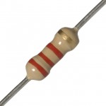
 Resistors look like candy-striped hot dogs. Their job is to limit current to keep sensitive electronics from being overloaded. If you break open a resistor, you’ll find a pile of graphite. If you have a digital multimeter, draw a line on a sheet of paper with a graphite pencil, and place one probe near the end of the line. You can measure the change in resistance along the line with your other multimeter probe!
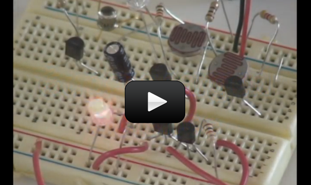
Make sure you’ve made the Light Flasher before starting this circuit. This circuit, the Audible Light Probe, is actually a very sensitive circuit that will emit all sorts of sounds reminiscent of junior high school boys locker rooms. The frequency from the speaker will change as the light intensity changes. One of the neat features about this circuit is that it will allow you to test different transistors (both PNP and NPN) to see (hear) the changes. You can also play with the capacitor and resistor values to change the range.
Click here for Unit 14 (Lesson 1) schematics.
TIP: If your tones won’t stop, or are too high to hear, try operating your circuit in a very dark room before adding the light. Can you get your speaker to *click*?
Materials:
- breadboard
- AA battery case
- 2 AA batteries
- LED
- CdS photocell
- transistor (2N2222A and 2N4403)
- 1k resistor
- 0.47μf electrolytic capacitor
- 8-ohm speaker
- jump wires
- wire strippers


This could be due to the wrong resistor values or the wrong transistors. I recommend rebuilding the circuit. Be sure to follow the values shown on the schematic titled “Audible Light Probe”. Which is available from the link above the parts list titled “Click here for Unit 14 (Lesson 1) schematics”
Ours is only activating the speaker when its dark. What did we do wrong?
Yes!!! The first circuit I got to work for me on the first try!! Fun annoying noise maker.
wooooooooow!!!!!!!!!!!!!!!!!!!